
Pumps move every liquid stream in a refinery or gas plant, from crude out of tankage to hot products leaving the columns, and compressors handle recycle hydrogen, fuel gas, flare gas and refrigerant. Selecting these machines is both a hydraulic problem and an economic one: the pump must deliver the required flow and head near its best efficiency point, with enough net positive suction head to avoid cavitation, and the compressor must deliver its head efficiently while staying away from surge. This guide works through one consistent example: the total dynamic head of a crude transfer pump, the NPSH margin of a hot condensate pump, the real saving from a variable speed drive when the system has a large static head, impeller trimming, polytropic compressor power, anti-surge recycle and mechanical seal selection.
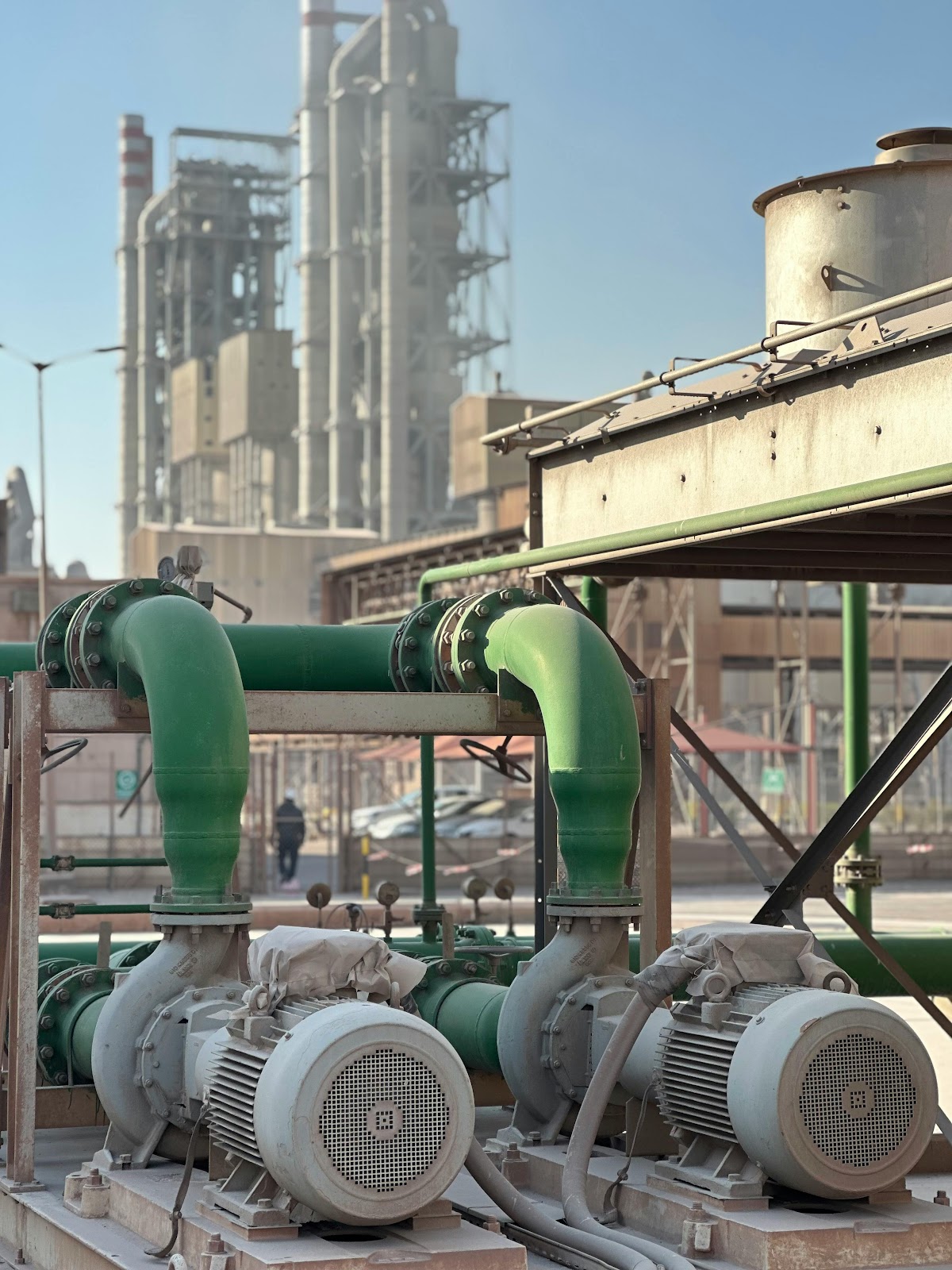
All plant data below (flows, pressures, elevations, efficiencies, prices) are a synthetic teaching example.
1. Centrifugal pump sizing
1.1 Total dynamic head
The head a pump must develop is the sum of the static elevation change, the pressure difference between the discharge and suction vessels, the friction loss in the piping and the change in velocity head:
Htotal = Hstatic + Hpressure + Hfriction + Hvelocity
Example: crude transfer from a desalter to the crude unit preheat train. The suction liquid level is 5.0 m above grade at atmospheric pressure; the delivery point is at 15.0 m elevation and 8.5 bar gauge. The flow is 50,000 barrels per stream day through NPS 8 Schedule 40 pipe (inside diameter 202.7 mm), with 350 m of equivalent length including fittings. The crude is taken at 860 kg/m³ and 8 mPa·s.
| Quantity | Calculation | Result |
|---|---|---|
| Volumetric flow | 50,000 × 0.158987 / 86,400 | 0.0920 m³/s |
| Velocity | 0.0920 / (π/4 × 0.2027²) | 2.85 m/s |
| Reynolds number | 860 × 2.85 × 0.2027 / 0.008 | 62,100 (turbulent) |
| Friction factor | Colebrook, ε = 0.046 mm (ε/D = 0.000227) | 0.0208 |
| Friction head | 0.0208 × (350/0.2027) × 2.85²/(2 × 9.81) | 14.9 m |
| Static head | 15.0 − 5.0 | 10.0 m |
| Pressure head | 850,000 / (860 × 9.81) | 100.8 m |
| Velocity head | 2.85²/(2 × 9.81), neglected | 0.4 m |
| Total dynamic head | 10.0 + 100.8 + 14.9 | 125.6 m, design 126 m |
The pressure term is 80% of the total, friction 12% and elevation 8%. This split is common in process service: the delivery pressure set by the downstream equipment, not the piping layout, dictates the pump head.
1.2 Power and driver
Phydraulic = ρ g Q H = 860 × 9.81 × 0.0920 × 125.6 = 97.5 kW
Pshaft = Phydraulic / η = 97.5 / 0.72 = 135 kW
The efficiency of 0.72 is an assumption for the example and should be replaced by the value read from the vendor curve. With a 10% driver margin (the required margin is set by the purchaser specification and API 610), the driver must be at least 149 kW, so the next standard rating of 160 kW (about 215 hp) is selected.
1.3 NPSH and cavitation
Cavitation starts when the local pressure at the impeller eye falls below the vapour pressure of the liquid. The available NPSH must exceed the NPSH required by the pump (NPSH3 on the vendor curve) with a margin:
NPSHA = (Psurface,abs − Pvapour) / (ρ g) + zliquid above pump − hf,suction
Example: a hot condensate pump drawing from a drum at 2.10 bar absolute. The condensate is at 120 °C, where IAPWS-IF97 gives a saturation pressure of 1.987 bar and a liquid density of 943 kg/m³. The liquid level is 3.5 m above the pump centreline and the suction line loses 0.8 m.
NPSHA = (210,000 − 198,700) / (943 × 9.81) + 3.5 − 0.8 = 1.23 + 2.70 = 3.93 m
With an assumed NPSH3 of 3.5 m, the margin is only 0.43 m and the ratio NPSHA/NPSH3 is 1.12. Recommended margins depend on the application and the suction energy of the pump; ANSI/HI 9.6.1 gives guidance and many purchaser specifications also impose a minimum margin in metres. For hot water service this margin would normally be judged too small, and the suction system should be improved.
Ways to raise the margin:
- Raise the drum or lower the pump: each metre of additional liquid height adds one metre of NPSHA.
- Subcool the liquid before the pump, which lowers its vapour pressure.
- Enlarge or shorten the suction line to cut the suction friction loss.
- Select a pump with a lower NPSH3, for example with an inducer or a larger impeller eye, after checking the vendor test data.
- Use a double-suction impeller. Each eye then handles half the flow; at equal suction specific speed, NPSH3 scales with Q2/3, so the requirement falls to about 0.63 of the single-suction value.
2. Affinity laws, variable speed and impeller trim
2.1 Affinity laws
For a given pump, flow scales with speed N, head with N² and power with N³. The same proportions are used approximately for small impeller trims at constant speed, with the diameter D in place of N.
Q2/Q1 = N2/N1 H2/H1 = (N2/N1)² P2/P1 = (N2/N1)³
The well known result that 80% speed needs only 0.8³ = 51% of the power applies only to a system with no static or pressure head, such as a closed circulation loop. The crude transfer system above has 110.8 m of fixed head out of 126 m, so the operating point moves along the system curve, not along an affinity parabola.
2.2 Variable speed drive versus throttling at 80% flow
To compare the two control methods, the example uses a synthetic pump curve H = 150 (N/N0)² − 2,878 Q² (shut-off head 150 m, passing through the design point) and the system curve H = 110.8 + 1,758 Q². Both cases are evaluated at 80% of design flow, Q = 0.0736 m³/s, with an assumed efficiency of 0.70.
| Case | Head developed | Speed | Shaft power |
|---|---|---|---|
| Throttle valve, full speed | 134.4 m (14.1 m burnt in the valve) | 100% | 119 kW |
| Variable speed drive | 120.3 m (system head) | 95.2% | 107 kW |
| Difference | 12.5 kW |
Over 8,760 h at an assumed electricity price of $0.08/kWh, the 12.5 kW saving is worth about $8,800 per year. At an assumed installed drive cost of $15,000, the simple payback is about 1.7 years. Applying the cube law blindly would have predicted about 37 kW and a payback of a few months, roughly three times too optimistic. Variable speed drives pay back fastest where friction dominates the system curve.
2.3 Impeller trim
If the process only needs 110 m at the design flow, the 16 m excess is burnt in the control valve. Trimming the impeller removes it:
D2/D1 ≈ (110/125.6)0.5 = 0.936
At 2,970 rpm (two-pole motor at 50 Hz) and a head coefficient gH/u² of about 0.5, the original impeller is roughly 320 mm, so the trimmed diameter is about 299 mm. Because the flow stays at its design value, the power falls in proportion to the head, not with the cube of the diameter:
P2 = 860 × 9.81 × 0.0920 × 110 / 0.72 = 118.6 kW, a saving of 16.9 kW
That is about $11,800 per year at the assumed price. Trim in steps and confirm against the vendor curve, because efficiency drops as the trim increases.
2.4 Specific speed
Ns = N Q0.5 / H0.75 (US units: rpm, US gpm, ft) Nq = N Q0.5 / H0.75 (rpm, m³/s, m)
For 0.0920 m³/s (1,458 US gpm) and 125.6 m (412 ft) at 2,970 rpm, Ns = 1,240 and Nq = 24. At 1,480 rpm the values would be 618 and 12, but the impeller would need a diameter of about 640 mm, which is why a two-pole speed is used here. Both values are in the radial-flow range; mixed-flow and axial impellers belong to much higher specific speeds. Low specific speed pumps have lower attainable efficiency, so the assumed 0.72 must be checked against the actual vendor curve. At 150% of design flow and the same head, Ns rises to about 1,520, still a radial design but with a wider impeller.
3. Compressors
3.1 Centrifugal or reciprocating
| Criterion | Centrifugal (API 617) | Reciprocating (API 618) |
|---|---|---|
| Flow | Large volumetric flows | Small to moderate flows |
| Pressure ratio | Moderate per stage, several stages per casing | High per stage |
| Gas molecular weight | Head per stage falls sharply for light gases such as hydrogen | Largely insensitive to molecular weight |
| Maintenance | Long run lengths between overhauls | Valves, packing and rings need regular attention |
| Low flow operation | Limited by surge, needs anti-surge recycle | No surge; capacity by unloaders, clearance pockets or speed |
The GPSA Engineering Data Book gives charts of the usual flow and pressure ranges for each type. For hydrogen-rich recycle gas at a low pressure ratio, both types are used; the choice is made on economics and reliability.
3.2 Polytropic power of a recycle gas compressor
Hp = [n/(n−1)] Zavg (R/MW) T1 [(P2/P1)(n−1)/n − 1], n/(n−1) = ηp k/(k−1)
Example: diesel hydrotreater recycle gas with 85 mol% H₂, 10% CH₄ and 5% C₂H₆, compressed from 60 to 65 bar absolute at 45 °C inlet, 200,000 Nm³/h, polytropic efficiency 0.78 and an assumed average Z of 1.02.
| Quantity | Result |
|---|---|
| Molecular weight | 0.85 × 2.016 + 0.10 × 16.04 + 0.05 × 30.07 = 4.82 kg/kmol |
| Ideal gas cp at about 320 K | 30.9 J/(mol·K), so k = 30.9/(30.9 − 8.314) = 1.37 |
| n/(n−1) | 0.78 × 1.37/0.37 = 2.90 |
| Pressure ratio | 65/60 = 1.083 |
| Polytropic head | 45.4 kJ/kg |
| Mass flow | 200,000 × 4.82 / 22.414 / 3,600 = 11.95 kg/s |
| Gas power | 11.95 × 45.4 / 0.78 = 696 kW |
| Driver power (mechanical efficiency 0.98) | 710 kW |
The power is modest because the pressure ratio is only 1.08. Raising the same mass flow from 1 to 60 bar in four intercooled stages (ratio 2.78 per stage, cooled back to 45 °C) would need about 2,700 kJ/kg of head and some 41 MW, which shows how strongly power depends on pressure ratio for a light gas.
Use the calculator below to repeat the calculation with your own data.
4. Surge and anti-surge control
Surge occurs when the flow through a centrifugal compressor falls below the stable limit of its map: the compressor can no longer develop the system back pressure, flow reverses, pressure collapses, forward flow resumes, and the cycle repeats. Repeated surge overloads thrust bearings, seals and impellers and heats the gas. The surge line comes from the vendor performance map, not from a general rule.
In this example the surge flow at the operating head is taken as 75% of design, 150,000 Nm³/h. The anti-surge controller keeps the flow above a control line set 10% to the right of surge, 165,000 Nm³/h, by opening a recycle valve from the cooled discharge back to suction.
| Item | Value |
|---|---|
| Control line | 1.10 × 150,000 = 165,000 Nm³/h |
| Minimum process demand (50% of design) | 100,000 Nm³/h |
| Maximum recycle | 165,000 − 100,000 = 65,000 Nm³/h |
| Compression power spent on recycle | 65,000/200,000 × 696 = 226 kW, removed in the recycle cooler |
Modern controllers measure flow and pressure ratio, compute the distance to the surge line continuously, and add a fast open-loop step on the recycle valve when the operating point moves rapidly toward surge.
5. Mechanical seals to API 682
API 682 classifies seals by category (1 for lighter-duty chemical pumps, 2 and 3 for API 610 pumps, with category 3 the most fully qualified) and by arrangement:
- Arrangement 1: one seal per cartridge.
- Arrangement 2: two seals with an unpressurized buffer liquid (for example Plan 52) or a dry containment seal; the buffer is below the seal chamber pressure, so a primary seal leak goes to the buffer system.
- Arrangement 3: two seals with a pressurized barrier fluid (for example Plan 53A, a reservoir pressurized with nitrogen); the barrier is above the seal chamber pressure, so any leakage is barrier fluid into the process.
Common flush plans:
| Plan | Description |
|---|---|
| 11 | Recirculation from pump discharge through an orifice to the seal chamber |
| 13 | Recirculation from the seal chamber through an orifice back to pump suction |
| 21 | As Plan 11, with a cooler |
| 32 | Clean flush injected from an external source |
| 52 | Unpressurized buffer liquid reservoir for Arrangement 2 |
| 53A | Barrier liquid reservoir pressurized by nitrogen for Arrangement 3 |
For a flammable crude containing H₂S, the standard selection procedure normally points to a dual seal, either Arrangement 2 or Arrangement 3, depending on the hazard assessment, the fluid volatility and site rules. The final choice should follow the API 682 selection procedure and the owner specification, and the cost of a seal upgrade should be weighed against the plant failure history.
Compression within a gathering system
Place equipment-level pump and compressor choices within gathering-network pressure and flow optimization.
Key points
- The crude transfer pump needs 126 m, 80% of it from the delivery pressure; shaft power is 135 kW and a 160 kW motor is selected.
- The hot condensate pump has 3.93 m NPSHA against 3.5 m NPSH3, a ratio of 1.12, too small for hot water service.
- The 51% power figure at 80% speed holds only for friction-only systems; with 88% fixed head, the drive saves 12.5 kW, not 37 kW.
- Trimming to remove 16 m of excess head saves 16.9 kW, proportional to the head reduction because the flow is unchanged.
- The hydrogen-rich recycle compressor needs 45.4 kJ/kg and 696 kW gas power at a ratio of 1.08.
- In API 682, Arrangement 2 uses an unpressurized buffer (Plan 52) and Arrangement 3 a pressurized barrier (Plan 53A).
For a related explanation, see our guide to Introduction to Petroleum Piping Systems.
References
- API Standard 610, Centrifugal Pumps for Petroleum, Petrochemical and Natural Gas Industries, 12th ed., American Petroleum Institute, 2021.
- API Standard 682, Pumps: Shaft Sealing Systems for Centrifugal and Rotary Pumps, 4th ed., American Petroleum Institute, 2014.
- API Standard 617, Axial and Centrifugal Compressors and Expander-compressors, 8th ed., American Petroleum Institute, 2014.
- API Standard 618, Reciprocating Compressors for Petroleum, Chemical, and Gas Industry Services, 5th ed., American Petroleum Institute, 2007.
- ANSI/HI 9.6.1, Rotodynamic Pumps: Guideline for NPSH Margin, Hydraulic Institute.
- GPSA Engineering Data Book, Section 13: Compressors and Expanders, Gas Processors Suppliers Association.
- J. F. Gülich, Centrifugal Pumps, Springer.
- C. F. Colebrook, Turbulent flow in pipes, Journal of the Institution of Civil Engineers, 11 (1939) 133 to 156.
- IAPWS, Revised Release on the IAPWS Industrial Formulation 1997 for the Thermodynamic Properties of Water and Steam.
Related reading and community
Questions about pump or compressor selection for a specific service? Join our Telegram group for rotating machinery discussions, or visit our YouTube channel for step-by-step tutorials on pump head, NPSH and compressor surge.