
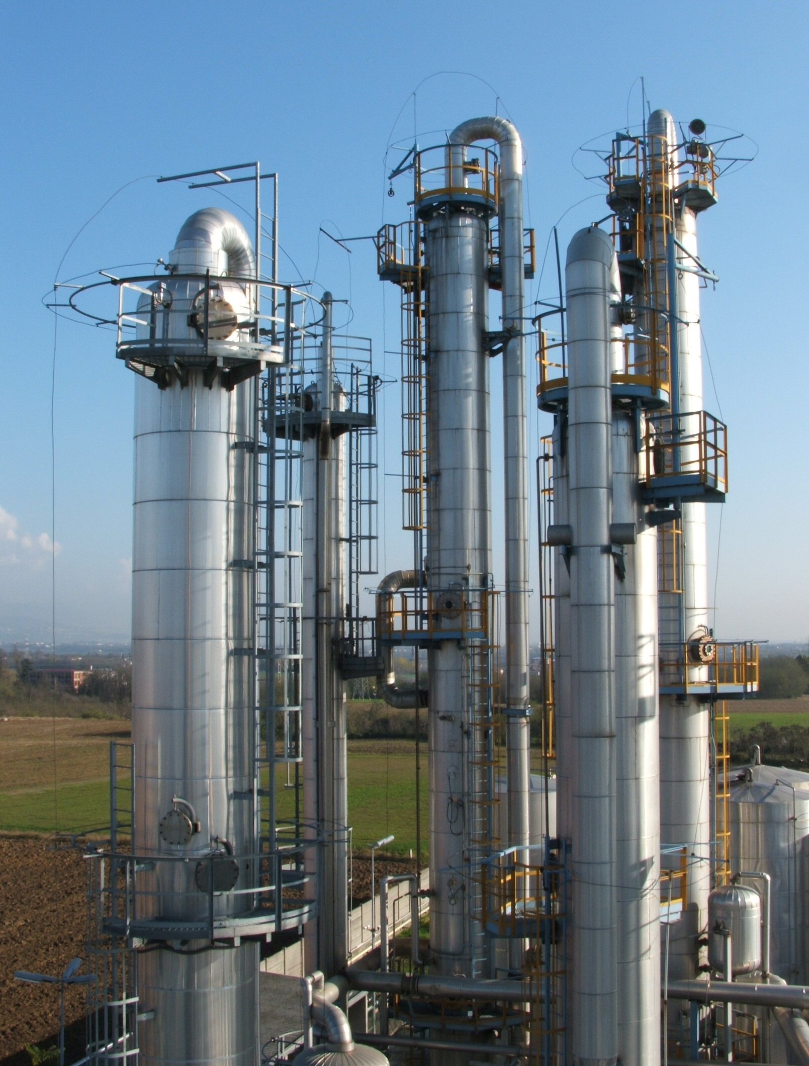
The vacuum distillation unit (VDU) processes the atmospheric residue left by the crude unit. By lowering the pressure, it vaporizes heavy gas oils at temperatures the oil can tolerate without excessive thermal cracking, producing light and heavy vacuum gas oil (LVGO, HVGO) for the FCC or hydrocracker, and a vacuum residue for coking, visbreaking, solvent deasphalting or bitumen. This guide explains the physics, sizes a column with a synthetic example that continues our crude distillation guide.

1. Why vacuum lowers the required temperature
The Clausius-Clapeyron equation gives a first estimate of how boiling temperature falls with pressure:
1/T2 = 1/T1 − (R/ΔHv) ln(P2/P1)
For a fraction with an atmospheric equivalent boiling point (AEBP) of 500°C and an assumed ΔHv of 60 kJ/mol, the boiling temperature is about 244°C at 10 mbar, 271°C at 20 mbar and 301°C at 40 mbar. For a 565°C AEBP fraction (ΔHv assumed 70 kJ/mol) it is about 330°C at 20 mbar and 361°C at 40 mbar. Because ΔHv changes with temperature and petroleum fractions are mixtures, refiners use the Maxwell-Bonnell correlation (API Technical Data Book, ASTM D1160 conversions) or a simulator rather than this constant-ΔHv estimate.
Thermal cracking depends on both temperature and residence time, not on a single threshold. Vacuum heaters therefore use high velocities and coil steam to limit residence time, and stripping steam lowers the hydrocarbon partial pressure in the flash zone, which raises the vaporization achieved at a given temperature.
2. Pressure profile
Pressure is lowest at the top of the column and highest in the flash zone, because the vapor must flow up through the internals. Modern units use structured or grid packing instead of trays, since each tray would add several millibar of pressure drop. A realistic synthetic profile is about 15 mbar at the column top and about 40 mbar in the flash zone, with the vacuum system holding the top pressure while removing non-condensable gases, stripping steam that the overhead condensers do not condense, and air leakage. A design that requires 1 mbar at the vacuum system inlet would be impractical.
3. Column diameter
Synthetic case: the 52,500 BPSD of atmospheric residue from the crude unit example, density 920 kg/m³, or 88.9 kg/s. Assume 47.6 wt% vaporizes as vacuum gas oil (42.3 kg/s, molecular weight 350) with stripping steam equal to 1 wt% of the feed (0.89 kg/s), at 40 mbar and 410°C in the flash zone. Steam is light, so it counts heavily in the vapor volume:
Mmix = (42.3 + 0.89) / (42.3/350 + 0.89/18) = 254 kg/kmol; ρV = 4,000 × 254 / (8,314 × 683) = 0.179 kg/m³
Vapor flow = 43.2 / 0.179 = 242 m³/s. With an assumed packing capacity factor C = 0.08 m/s and liquid density 900 kg/m³, uflood = 0.08 × √(900/0.179) = 5.7 m/s; at 70% of flood the velocity is 4.0 m/s, the area 60.8 m² and the diameter about 8.8 m. Ignoring the steam would understate the vapor flow by about 30%. Vacuum columns are usually wider than the atmospheric column of the same refinery, because the vapor is so much less dense; this is why they often have a wide lower section and a narrower top.
4. The wash section
Between the flash zone and the HVGO draw, a wash bed of grid or structured packing is sprayed with HVGO. It removes entrained droplets of residue, which carry metals (nickel, vanadium) and carbon residue that poison FCC and hydrocracking catalysts. The liquid leaving the bottom of the bed, often called slop wax or overflash, is usually withdrawn or recycled rather than returned to the HVGO product.
The main design risk is a dry bed. If too little wash liquid reaches the lower part of the bed, the packing cokes, pressure drop rises and HVGO quality falls. Wash rate is therefore set from licensor or published guidance on the minimum wetting rate at the bottom of the bed, with spray coverage checked by the distributor supplier. On the 8.8 m column above (60.8 m² area), every 0.5 m³/h/m² of wetting rate corresponds to about 30 m³/h of liquid. Wash rates and temperatures should be confirmed for each design, not taken from a generic rule.
5. Vacuum system
Most units use two or three stages of steam ejectors with condensers between stages; many also use a liquid ring vacuum pump as the last stage. A liquid ring pump alone cannot reach the top pressures of a deep-cut column, so hybrid systems combine ejectors for the low-pressure stages with a mechanical pump at the discharge end to save motive steam.
Motive steam consumption must come from the ejector vendor's design for the actual load (non-condensables, uncondensed steam and an air leakage allowance from Heat Exchange Institute guidance). For a sense of scale only: 20 t/h of motive steam at an assumed $20/t costs 20 × 8,760 × 20 = about $3.5 million per year, which is why condenser performance, air leakage and cooling water temperature are monitored closely.
6. Stripping steam
- Bottom stripping steam removes gas oil from the vacuum residue. Removing the lighter material raises the residue's flash point and increases gas oil recovery.
- Coil steam in the heater increases velocity and reduces residence time and coking in the tubes.
- Some units are designed "dry", without stripping steam, to reduce the vapor load and the condensing duty; they rely on a lower flash zone pressure instead.
7. Deep cut: yield against quality
Raising the HVGO/residue cut point increases gas oil yield, but the extra material carries more carbon residue (CCR) and metals. Synthetic case: moving the cut from 565 to 600°C AEBP raises HVGO from 6,050 to 7,700 BPSD (+1,650 BPSD), while HVGO CCR rises from 0.8 to 1.8 wt%. If HVGO is worth $33/bbl more than vacuum residue, the gross gain is 1,650 × 33 = $54,450/day, about $19.9 million per year.
That gain must be compared with the effect on the conversion unit. If the HVGO is blended into a 30,000 BPSD FCC feed whose other components have 0.3 wt% CCR, the blend CCR rises from about 0.40 to 0.69 wt% (volume-weighted approximation). The FCC model, not a rule of thumb, then gives the extra coke, the change in regenerator temperature, the catalyst addition needed for the higher metals and the loss of liquid yield. Only the net value across the VDU and the conversion units shows whether the deeper cut pays.
References
- API Technical Data Book (Maxwell-Bonnell vapor pressure correlation)
- ASTM D1160 (distillation at reduced pressure)
- Heat Exchange Institute, Standards for Steam Jet Vacuum Systems
- H.Z. Kister, Distillation Operation (McGraw-Hill, 1990)
Related reading and community
Questions or field experience to share? Join the PetroSmart Telegram group, watch worked examples on the PetroSmart Academy YouTube channel and follow us on Facebook.